In today's fast-paced and technology-driven world, a well-designed and implemented structured cabling system is vital for businesses to achieve optimal performance and scalability. Whether it's transmitting data, voice, or video, a structured cabling system serves as the backbone of any organization's network infrastructure. By organizing and standardizing the cabling infrastructure, businesses can ensure reliable connectivity and efficient communication.
A structured cabling system plays a crucial role in any modern network infrastructure. It provides the foundation for the transmission of data, voice, and video signals throughout an organization. By organizing and standardizing the cabling infrastructure, businesses can ensure reliable connectivity and efficient communication. However, to fully realize these benefits, it is equally important to know how to design a structured cabling system that aligns with both current operations and future growth—not just install cables, but plan for performance, redundancy, and scalability from the start.
With the increasing reliance on technology and the growing demand for high-speed data transmission, a well-designed structured cabling system is essential. It allows for easy scalability and adaptability to future technological advancements, reducing the need for costly upgrades or replacements.
Furthermore, a structured cabling system improves network performance and reduces downtime. With proper cable management and organization, troubleshooting and maintenance become easier, resulting in faster problem resolution and minimized disruptions to business operations.
Overall, understanding the importance of a structured cabling system is crucial for businesses aiming to optimize their network infrastructure and ensure seamless communication and data transmission.
Before designing a structured cabling system, it is essential to thoroughly assess and plan for your organization's cabling needs. This involves considering factors such as the current and future network requirements, the physical layout of the building, and the types of devices that will be connected.
Start by conducting a comprehensive audit of your existing infrastructure to identify any bottlenecks, outdated components, or areas for improvement. Evaluate the bandwidth requirements of your network and estimate the number of devices that will be connected to ensure sufficient capacity for your structured cabling system design.
Additionally, consider the future expansion plans of your organization. Will you be adding more employees or devices? Will there be new technologies that require additional cabling? By anticipating future needs, you can design a cabling system that is scalable and adaptable.
Lastly, consult with experienced professionals or network consultants who specialize in structured cabling design. They can provide valuable insights and recommendations based on industry best practices and ensure that your cabling system meets both current and future requirements.
The design phase of a structured cabling system is crucial for achieving optimal performance and scalability. Consider the following best practices when designing your cabling infrastructure:
1.Use a hierarchical design approach: Divide your cabling system into logical sections, such as the entrance facility, equipment room, telecommunications room, and work area. This hierarchical design simplifies troubleshooting and maintenance.
2. Plan for cable pathways: Proper cable management is essential for maintaining a clean and organized cabling infrastructure. Plan for cable pathways, such as conduits, cable trays, and raceways, to ensure cables are neatly routed and protected.
3. Follow industry standards: Adhere to recognized structured cabling standards, such as the TIA/EIA-568 or ISO/IEC 11801, when designing your cabling system. These standards define the requirements for cable performance, connectors, and termination techniques, all of which are foundational to a robust structured cable plants design.
4. Allow for future expansion: Design your cabling system with scalability in mind. Leave room for additional cables and equipment to accommodate future growth and technological advancements.
By following these best practices, you can ensure that your structured cabling system is efficient, organized, and capable of supporting your organization's evolving needs.
To correctly execute an it structured cabling layout, your infrastructure blueprint must map out the six essential subsystems defined by international cabling engineering bodies:
Entrance Facility (EF): The exact point where the service provider's external plant cabling connects with the building's internal backbone network.
Equipment Room (ER): The centralized space housing main cross-connects, core switches, servers, and vital network protection devices.
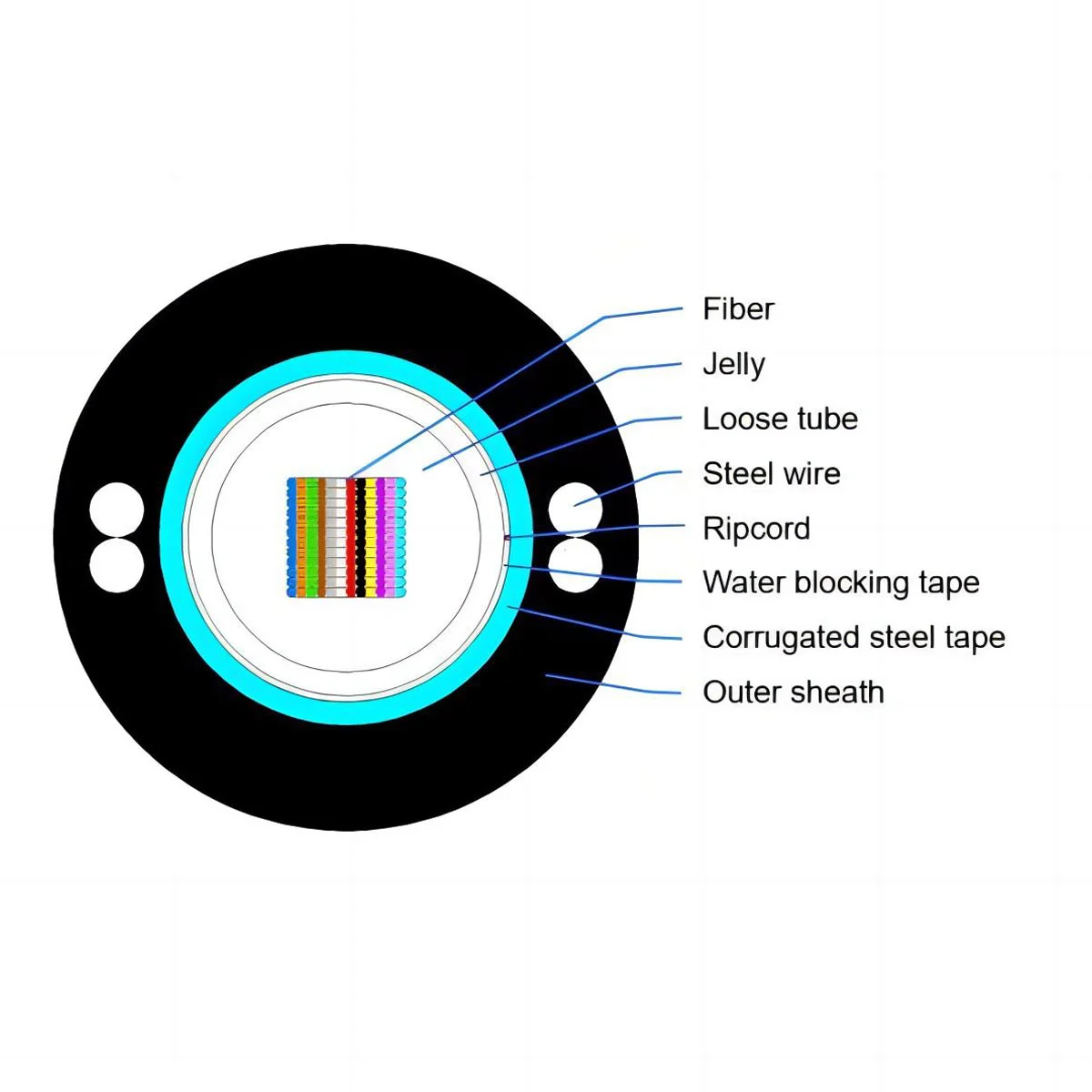
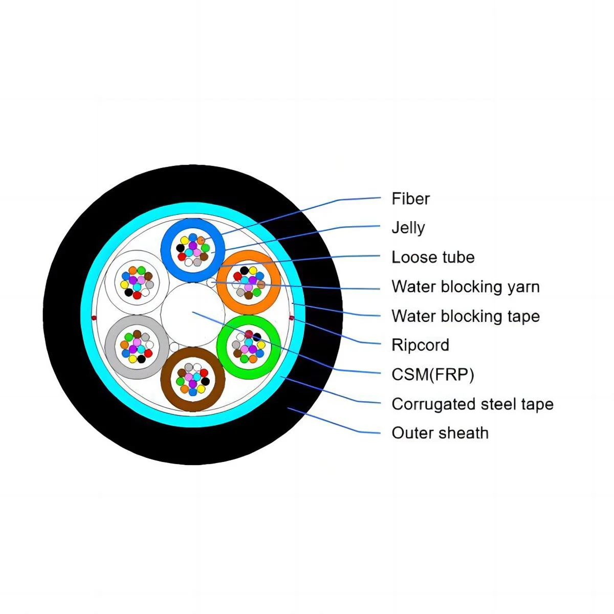
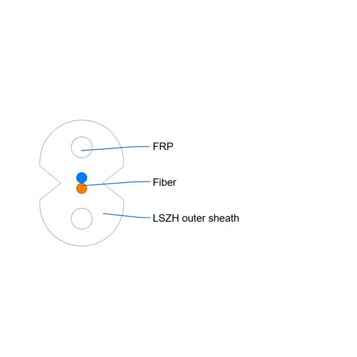
Backbone Cabling (Vertical): The high-capacity links (typically single-mode or multi-mode fiber optic cables) connecting the main Equipment Room to various Telecommunications Rooms throughout the facility.
Telecommunications Room (TR): Enclosed architectural spaces containing patch panels, horizontal cross-connects, and intermediate switches that distribute signals to individual floors.
For shielded Category 6 installations, a cat6 ftp patch panel can be used to organize and terminate the corresponding network links within the telecommunications room.
Horizontal Cabling: The data paths stretching from the TR patch panel directly to the work area outlets. This typically utilizes premium Category 6/6A copper links like CAT6 FTP Patch Cords.
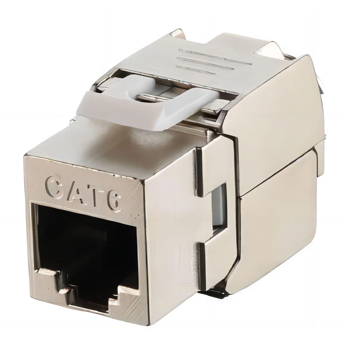
Work Area Components: The final termination equipment connecting end-user devices (computers, Wi-Fi APs, VoIP phones) to the horizontal wall outlets via modular CAT6 FTP Keystone Jacks.
Adhering to recognized engineering benchmarks guarantees universal equipment interoperability and certified performance validation.
| Standardization Body | Document / Regulation Reference | Primary Focus Areas in Cable Design |
| TIA/EIA | TIA/EIA-568.2-D | Balanced Twisted-Pair Telecommunications Cabling and Components Standards |
| ISO/IEC | ISO/IEC 11801 | Information technology — Generic cabling for customer premises |
| ANSI/TIA | TIA-569-E | Telecommunications Pathways and Spaces Standards |
| BICSI | ITSIMM / TDMM Guidelines | Information Technology Systems Installation & Design Best Practices |
Q1: What is the main purpose of a structured cabling system?
A1: The primary purpose of a structured cabling system is to provide a standardized, highly organized infrastructure that supports multi-vendor telecommunications environments. By dividing the system into six distinct subsystems, it eliminates raw connection dependencies, maximizes data transmission speeds, and allows businesses to easily move, add, or change hardware configurations with minimal network downtime.
Q2: What are the primary benefits of structured cabling over point-to-point wiring?
A2: Unlike point-to-point wiring—which creates chaotic "spaghetti cables" that trap heat and complicate maintenance—structured cabling offers superior cable management, lower long-term operational costs, and immediate isolation of network faults. It also ensures seamless scalability, meaning your facility's backbone can adapt to future technological advancements without requiring a complete infrastructural overhaul.
Q3: Why is industry standards compliance (like TIA-568) critical during the design phase?
A3: Adhering to standards such as ANSI/TIA-568.2-D and ISO/IEC 11801 ensures universal equipment interoperability, guaranteed bandwidth performance (e.g., up to 250MHz for Category 6 systems), and structural safety compliance. Designing your network without these criteria can lead to severe impedance mismatching, signaling cross-talk, and failure to support high-power Power over Ethernet (PoE) installations.
Q4: How far can a copper horizontal structured cable run stretch?
A4: According to global standard regulations, the maximum continuous length for horizontal twisted-pair copper cabling is 90 meters (295 feet) of permanent link. An additional combined allowance of 10 meters is granted for patch cords within the Telecommunications Room and the work area, bringing the total channel limit to 100 meters. If your architecture demands longer distances, a high-capacity optical fiber backbone system must be utilized.


 Call us on:
  Email Us:
  No.10 Xumutang Road, Lishui Economic Development Zone, Nanjing, China
 EN
EN
 fr
fr  de
de  es
es  ru
ru  pt
pt  ar
ar  vi
vi  th
th  id
id