Structured cabling is a standardized approach to organizing the copper and fiber infrastructure that supports data, voice, video and other network services within a building, campus or data center. Instead of connecting devices with isolated point-to-point cables, a structured cabling system divides the network into organized subsystems that are easier to manage, expand and upgrade.
A complete system may include communications cables, backbone cabling, patch panels, keystone jacks, patch cords, wall outlets and cable management components. Understanding how these elements work together helps network planners, installers and project buyers select an infrastructure that meets current performance requirements while leaving room for future expansion.
Structured cabling provides an organized infrastructure for data, voice and network communication rather than relying on individual point-to-point connections.
A structured cabling system is commonly organized around six subsystems: entrance facilities, equipment rooms, backbone cabling, telecommunications rooms, horizontal cabling and work areas.
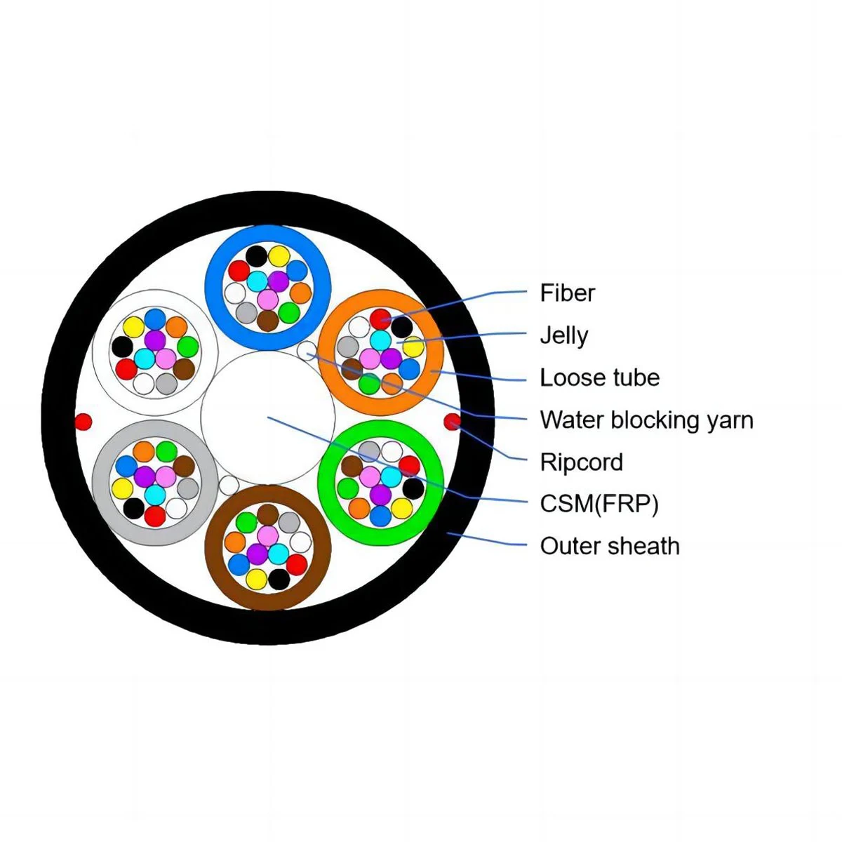
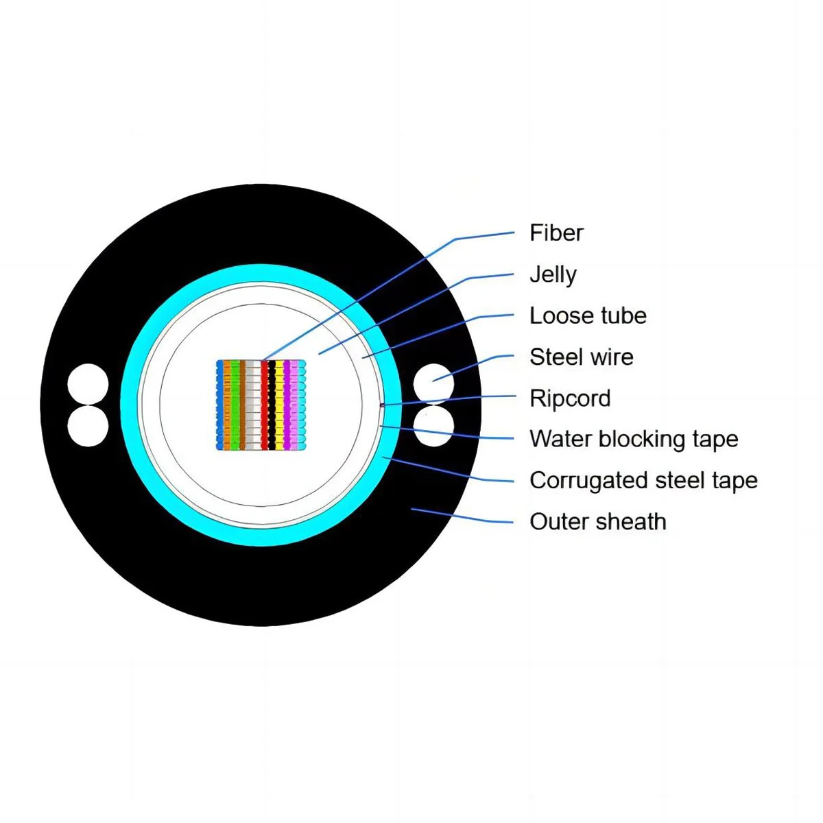
Typical components include CAT5E, CAT6 and CAT6A copper cables, fiber optic cables, patch panels, keystone jacks, patch cords, wall plates and cable management products.
Copper is commonly used for horizontal LAN and PoE connections, while fiber is often selected for backbones, longer distances and high-bandwidth network links.
Standards such as ANSI/TIA-568 and ISO/IEC 11801 provide important guidance for structured cabling design, components and performance.
Cable type should be selected according to network speed, transmission distance, EMI conditions, installation environment, PoE requirements and future capacity.
Structured cabling is a standardized telecommunications cabling infrastructure designed to support multiple hardware and network applications through an organized hierarchy of cables, connection points and distribution areas. The goal is not simply to install cables, but to create a network infrastructure that can be managed, tested, modified and expanded systematically.
Unlike a point-to-point system, where individual devices may be connected directly with long cable runs, structured cabling creates defined distribution points. Network equipment connects through patch panels, backbone or horizontal cables, outlets and patch cords before reaching the final device.
HEDOT's cabling system solutions include the main copper connectivity components used to build this type of network infrastructure.
A structured cabling system is commonly organized into six functional subsystems. Together, they create a logical path from external network services and centralized equipment to individual work areas and connected devices.
The entrance facility is where external telecommunications services enter the building and transition into the internal cabling infrastructure. It may include service-provider cables, protection equipment and connection hardware.
The equipment room accommodates centralized telecommunications and network equipment such as switches, routers, servers, racks and cross-connect hardware.
Backbone cabling interconnects equipment rooms, telecommunications rooms and entrance facilities. Fiber optic cable is frequently selected for high-capacity backbone links and longer transmission distances.
A telecommunications room provides a distribution point between backbone and horizontal cabling. Typical equipment includes switches, racks, patch panels and cable management hardware.
Horizontal cabling connects the telecommunications room with network outlets in the work area. CAT5E, CAT6 and CAT6A copper cables are commonly used for these links.
The work area is the final connection point for computers, IP phones, wireless access points and other devices. Wall plates, keystone jacks and patch cords are commonly used here.
| Subsystem | Primary Function | Typical Components |
|---|---|---|
| Entrance Facilities | Connect outside services | Carrier cables, protection and connection hardware |
| Equipment Room | Centralize network equipment | Switches, routers, servers and racks |
| Backbone Cabling | Connect distribution spaces | Fiber and copper backbone cables |
| Telecommunications Room | Distribute local network connections | Patch panels, switches and cable managers |
| Horizontal Cabling | Connect telecom rooms to outlets | CAT5E, CAT6 and CAT6A cabling |
| Work Area | Connect end-user devices | Jacks, wall plates and patch cords |
The six subsystems describe how the infrastructure is organized, while physical cabling and connectivity products create the actual transmission and connection paths. The following components are commonly found in commercial structured cabling projects.
Copper communications cables such as CAT5E, CAT6 and CAT6A are used for Ethernet and horizontal cabling applications. Shielded cable designs such as CAT6 FTP cables can be considered where electromagnetic interference is an important design factor.
Patch panels provide centralized cable termination and administration inside equipment racks or telecommunications rooms. They make network changes easier because equipment connections can be reorganized through patching rather than changing permanent cable runs.
Keystone jacks create modular termination points for network outlets, wall plates and patch panels. The jack category and shielding design should match the selected copper cabling system.
Patch cords provide flexible connections between switches, patch panels, outlets and end devices. Using components that match the cable category and shielding design helps maintain consistent channel performance.
Wall plate and cable management solutions help organize network outlets and cable routing while making future maintenance, identification and expansion easier.
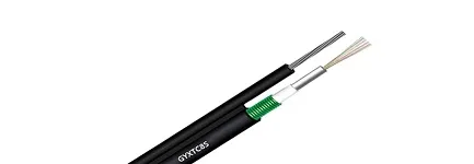
Fiber optic cables and components are frequently used for backbone links and high-capacity networks. Components such as a fiber optic patch panel provide organized fiber termination, distribution and administration within equipment rooms and data centers.
Copper and fiber optic cabling both have important roles in structured cabling systems. Copper is commonly used for horizontal connections to work areas and Ethernet devices, while fiber is frequently used for backbone links, longer distances and high-bandwidth network infrastructure.
In many enterprise buildings and data centers, the most practical architecture is not copper or fiber, but a combination of both.
| Comparison | Copper Cabling | Fiber Optic Cabling |
|---|---|---|
| Common Types | CAT5E, CAT6, CAT6A | OS2, OM3, OM4, OM5 |
| Typical Role | Horizontal LAN and device connections | Backbone and high-capacity links |
| Distance | Commonly used for shorter building links | Suitable for substantially longer links depending on fiber type and application |
| Bandwidth | Suitable for common enterprise Ethernet applications | Well suited to high-bandwidth backbone and data center applications |
| EMI Resistance | Performance depends on cable design, shielding and installation environment | Immune to electromagnetic interference |
| PoE | Can support Power over Ethernet | Standard optical fiber does not deliver electrical power |
Connecting office workstations and network outlets
Supporting IP phones, cameras or wireless access points with PoE
Using standard RJ45-based Ethernet equipment
The required distance and bandwidth fit the selected cable category
Building backbone or campus connections are required
Transmission distance exceeds practical copper limits
High-capacity data center links are being deployed
Electromagnetic interference is a major concern
The main advantage of structured cabling is that it creates a predictable infrastructure instead of a collection of unrelated cable connections. This becomes increasingly important as networks grow, equipment changes and additional users or devices are added.
Defined pathways, patching points and labels make connections easier to identify, maintain and troubleshoot.
New devices, work areas and network equipment can be added without redesigning the complete infrastructure.
Patch-based administration makes many equipment and workstation changes easier to manage.
A properly planned cabling architecture can provide pathways and capacity for future network upgrades.
Structured cabling systems should be designed with recognized cabling standards in mind. Standards provide a common framework for cabling architecture, component performance, installation practices and interoperability.
| Standard | Relevance |
|---|---|
| ANSI/TIA-568 | A major telecommunications cabling standards family covering commercial building cabling and related copper and optical fiber requirements. |
| ISO/IEC 11801 | An international generic cabling framework for customer premises, with parts addressing different environments and applications. |
| TIA-942 | Relevant to telecommunications infrastructure within data center environments. |
Projects using fiber should also consider the standards applicable to the selected optical fiber, cable and connectivity components. See our fiber optic standards guide for additional selection guidance.
Selecting a structured cabling system should begin with application requirements rather than choosing a cable category in isolation. The following factors help determine an appropriate architecture.
Consider the applications that must be supported today and whether the infrastructure may need to support faster Ethernet during its expected service life.
Short building links may be suitable for copper, while longer backbone and campus routes may make fiber a more appropriate choice.
Indoor offices, industrial environments, equipment rooms and outdoor routes can require different cable constructions, fire ratings, shielding designs and mechanical protection.
Where electromagnetic interference is a concern, shielded copper systems may be considered. Shielding should be treated as a complete channel design involving compatible cables, jacks, panels, patch cords and grounding practices.
Wireless access points, IP cameras, phones and other devices may use Power over Ethernet, making copper channel design and thermal considerations important.
Allow space in pathways, racks, patch panels and telecommunications rooms so new connections can be added without rebuilding the entire cabling infrastructure.
Structured cabling can be adapted to different building types and network architectures. Common applications include:
For high-speed fiber infrastructure, explore HEDOT's data center solutions for 40G, 100G and 400G network applications.
Structured cabling is an organized, standards-based telecommunications infrastructure that uses defined cabling subsystems and connection hardware to support network, voice, data and related communication services.
The six commonly recognized subsystems are entrance facilities, equipment rooms, backbone cabling, telecommunications rooms, horizontal cabling and work areas.
Common components include copper and fiber optic cables, patch panels, keystone jacks, patch cords, racks, network outlets, wall plates and cable management hardware.
CAT6 cable can be one component of a structured cabling system, particularly for horizontal Ethernet connections. A complete system also includes termination, patching, pathways, work-area connections and other infrastructure.
It depends on the application. Copper is commonly used for horizontal LAN connections and PoE devices, while fiber is often preferred for longer-distance backbone and high-capacity network links. Many projects use both.
ANSI/TIA-568 and ISO/IEC 11801 are two important structured cabling standards families. Additional standards may apply depending on whether the project involves commercial buildings, data centers, industrial facilities, optical fiber or other specific environments.
Structured cabling provides the physical foundation for reliable and scalable network infrastructure. By organizing cabling into defined subsystems and selecting compatible cables, patch panels, jacks, patch cords and management components, businesses can simplify maintenance while preparing the network for future equipment and bandwidth requirements.
The most suitable architecture depends on transmission speed, distance, environment, shielding, PoE requirements and future expansion. Copper and fiber should therefore be evaluated as complementary technologies rather than treated as universal replacements for one another.
Explore HEDOT cabling system products or contact our team to discuss cable categories, shielding, patching, fiber connectivity and project requirements.
Contact HEDOT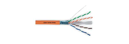
 Call us on:
  Email Us:
  No.10 Xumutang Road, Lishui Economic Development Zone, Nanjing, China
 EN
EN
 fr
fr  de
de  es
es  ru
ru  pt
pt  ar
ar  vi
vi  th
th  id
id