

 EN
EN
 fr
fr  de
de  es
es  ru
ru  pt
pt  ar
ar  vi
vi  th
th  id
id 
In fiber optic cabling projects, patch cords and patch panels are not just accessories. They are key parts of the complete optical fiber channel. If the cable, connector, patch cord and patch panel are not selected correctly, the network may face higher insertion loss, polarity mistakes, poor port management or unstable transmission performance.
TIA-568.3, also known as ANSI/TIA-568.3, is an important optical fiber cabling standard for premises cabling systems. It helps define performance, transmission, testing and component requirements for optical fiber cables, connectors, connecting hardware and patch cords. For buyers, installers and system integrators, understanding this standard can make fiber patch cord and fiber patch panel selection more reliable.
If you need a wider overview of IEC, TIA, ISO/IEC and ITU-T references, you can also read our fiber optic standards guide for cable selection and network projects.
What Is TIA-568.3?
TIA-568.3 is part of the TIA-568 structured cabling standard family. Unlike copper cabling standards that focus on twisted-pair categories such as Cat6 and Cat6A, TIA-568.3 focuses on optical fiber cabling and components used in premises cabling systems.
For fiber optic projects, this standard is especially relevant to components such as optical fiber cables, connectors, connecting hardware, patch cords and patch panels. It also helps buyers and installers understand testing, transmission performance and polarity requirements in a complete fiber cabling channel.
You can refer to the official ANSI/TIA-568.3-E optical fiber cabling standard page for more details about its scope and updates.
| Area | What TIA-568.3 Covers | Why Buyers Should Care |
|---|---|---|
| Optical fiber cable | Premises optical fiber cabling performance and transmission requirements | Helps confirm whether the cable is suitable for the planned network channel. |
| Connectors | Connector performance and compatibility requirements | Helps reduce connection loss and compatibility problems. |
| Connecting hardware | Components such as patch panels and adapter panels | Helps keep fiber links organized, testable and maintainable. |
| Patch cords | Fiber patch cord performance and channel connection requirements | Helps ensure stable equipment-side and cross-connect connections. |
| Polarity and testing | Connectivity, polarity and test requirements | Helps avoid transmit-to-transmit or receive-to-receive connection errors. |
Why TIA-568.3 Matters for Fiber Patch Cords
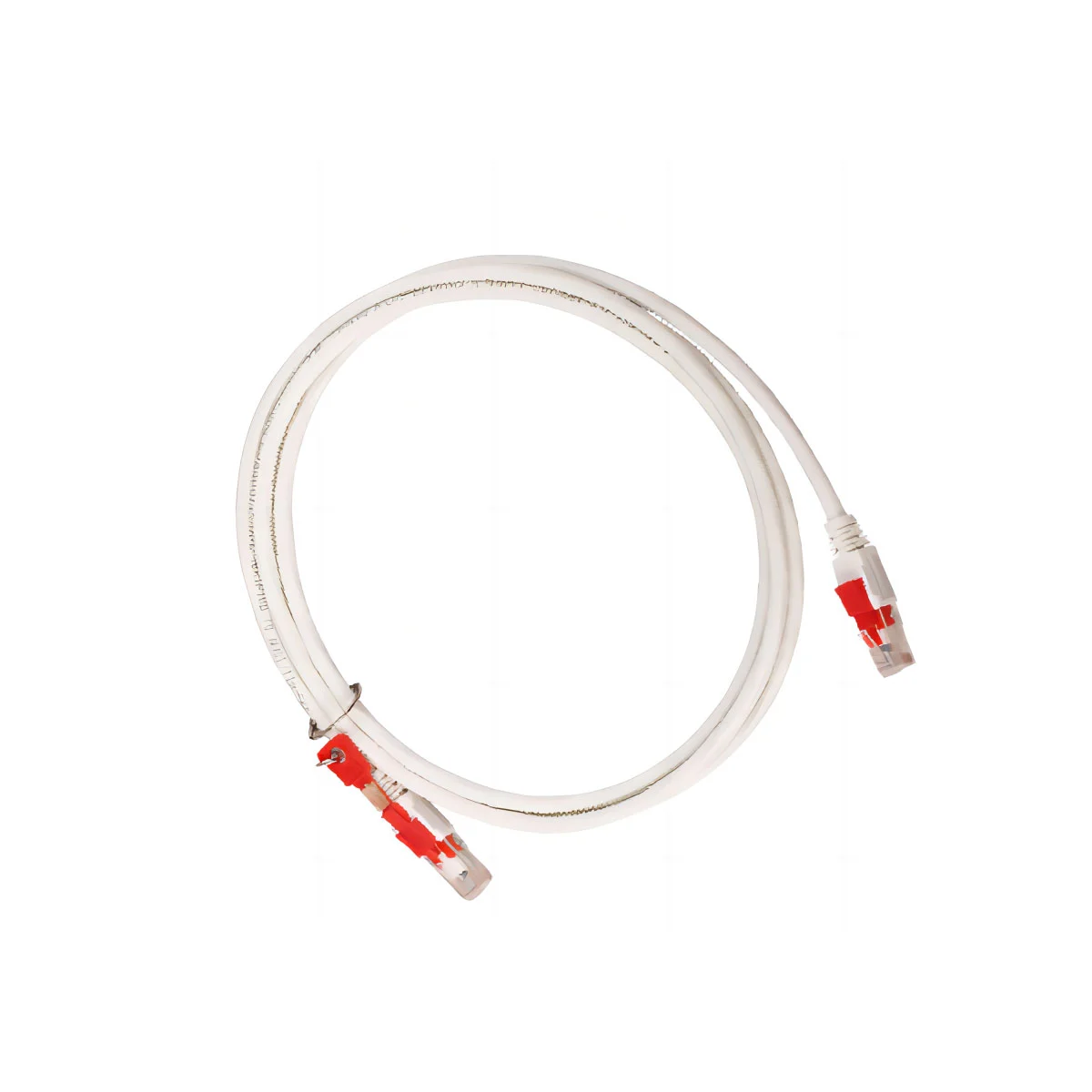
A fiber patch cord is used to connect optical equipment, patch panels, adapters, transceivers or other fiber network components. In many projects, buyers pay attention to fiber type and connector type, but they may ignore insertion loss, polarity, jacket material, length management and compatibility with the patch panel.
TIA-568.3 is useful because it reminds buyers that patch cords are part of the complete optical fiber cabling channel. A patch cord should not be selected only by color or price. It should match the fiber type, connector interface, performance requirement and cabling layout.
Fiber Patch Cord Selection Factors
| Selection Factor | What to Confirm | Why It Matters |
|---|---|---|
| Fiber type | Single-mode or multimode fiber | The patch cord must match the optical link and transmission equipment. |
| Connector type | LC, SC, FC, ST or MPO/MTP connector | The connector must match patch panels, adapters and transceivers. |
| Polarity | Simplex, duplex or array connectivity polarity | Correct polarity ensures transmitter and receiver alignment. |
| Insertion loss | Connector and channel loss requirements | Lower loss supports more reliable optical transmission. |
| Jacket material | PVC, LSZH or other project-required jacket | Indoor, data center and public building projects may require different jacket materials. |
| Length and management | Proper patch cord length and routing | Good length planning reduces bending, clutter and maintenance problems. |
Why TIA-568.3 Matters for Fiber Patch Panels
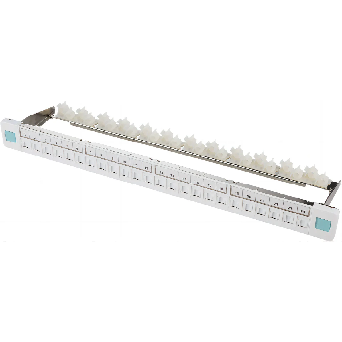
A fiber patch panel is used to organize, terminate and manage fiber optic connections in racks, cabinets, telecom rooms and data centers. It helps installers create a clean and manageable connection point between incoming fiber cables, patch cords and active equipment.
From a TIA-568.3 perspective, a fiber patch panel belongs to connecting hardware. Its role is not only physical organization. It also affects connector compatibility, cable management, testing access, polarity control and long-term maintenance.
For project buyers, choosing the right fiber optic patch panel helps make the whole fiber cabling channel easier to install, test, expand and troubleshoot.
Fiber Patch Panel Selection Factors
| Selection Factor | What to Confirm | Buyer Benefit |
|---|---|---|
| Port capacity | 12, 24, 48, 96 ports or project-specific capacity | Supports current fiber count and future expansion. |
| Connector compatibility | LC, SC, MPO/MTP or adapter type | Ensures compatibility with patch cords and equipment interfaces. |
| Rack compatibility | 19-inch rack mount or cabinet installation | Fits standard network racks and data center cabinets. |
| Cable management | Splice tray, cable entry, bend radius control and labeling | Improves installation quality and maintenance efficiency. |
| Polarity planning | Duplex or MPO/MTP polarity method | Reduces connection errors in high-density fiber networks. |
| Application environment | Telecom room, data center, enterprise network or FTTH distribution | Helps match the patch panel type with project conditions. |
Fiber Patch Cords and Patch Panels Work as One Channel
Fiber patch cords and patch panels should not be selected separately. In a complete optical fiber cabling system, the patch panel provides termination and management, while the patch cord provides the equipment-side or cross-connect connection.
If the patch cord connector type, fiber type or polarity does not match the patch panel, the network may face connection failure or performance issues. If the patch panel does not provide proper cable management, patch cords may be bent, crowded or difficult to maintain.
| Channel Component | Main Role | What to Match |
|---|---|---|
| Backbone or horizontal fiber cable | Provides the main optical transmission path | Fiber type, fiber count, cable structure and route environment |
| Fiber patch panel | Terminates, organizes and manages fiber links | Port count, adapter type, rack design and cable management |
| Fiber patch cord | Connects patch panels, transceivers and optical equipment | Connector type, polarity, fiber type, length and jacket material |
| Adapter or coupler | Provides connector-to-connector mating | Connector format, insertion loss and compatibility |
| Testing and labeling | Verifies and maintains the cabling channel | Test method, link identification and maintenance plan |
For a complete fiber cabling system, buyers can also consider matching fiber optic jumper coupler products with patch panels, patch cords and fiber cables according to the project connector type and network layout.
How TIA-568.3 Supports Polarity Planning
Polarity is one of the most important issues in fiber optic cabling. A fiber link must correctly connect the transmitter at one end to the receiver at the other end. If polarity is wrong, the optical link may not work even if the cable and connectors are physically connected.
TIA-568.3 describes transition methods used to maintain optical fiber polarity and ensure connectivity between transmitters and receivers using simplex, duplex and array connectivity. This is especially important for duplex LC links and high-density MPO/MTP cabling systems.
| Connection Type | Polarity Concern | Buyer / Installer Action |
|---|---|---|
| Simplex connection | Single fiber path must connect correctly between two ports | Check port direction and equipment interface. |
| Duplex LC connection | Transmit and receive fibers must be crossed correctly | Use correct duplex patch cord orientation and verify the link. |
| MPO/MTP array connection | Multiple fibers must maintain correct channel mapping | Plan polarity method before buying trunk cables, cassettes and patch cords. |
| Patch panel connection | Port mapping must match documentation | Label patch panel ports and test the complete channel. |
Common Fiber Patch Cord and Patch Panel Mistakes
Many fiber network problems are caused not by the optical fiber itself, but by poor component matching, weak cable management or incorrect installation planning. The following mistakes are common in fiber patch cord and patch panel procurement.
| Common Mistake | Possible Problem | Better Practice |
|---|---|---|
| Choosing patch cords only by price | Higher insertion loss, poor connector quality or short service life | Check fiber type, connector quality, jacket material and performance requirements. |
| Ignoring connector compatibility | Patch cord cannot match patch panel, adapter or transceiver interface | Confirm LC, SC, FC, ST or MPO/MTP interface before ordering. |
| Using the wrong patch cord length | Too much cable slack or excessive bending in racks | Plan rack layout and select suitable patch cord length. |
| Ignoring polarity | Optical link does not work after installation | Confirm polarity method before installation and test the channel after connection. |
| Overcrowding patch panels | Difficult maintenance, bending stress and port confusion | Use proper cable management, labeling and port planning. |
| Not testing after installation | Hidden loss or connection problems remain in the network | Test and document the complete fiber cabling channel. |
How to Choose Fiber Patch Cords and Patch Panels for Your Project
When selecting fiber patch cords and patch panels, buyers should start from the network application, not from a single product name. A data center project, enterprise building, telecom room and FTTH distribution project may require different port density, connector type, cable management design and patch cord specifications.
| Project Need | Patch Cord Consideration | Patch Panel Consideration | Recommended HDC Product Direction |
|---|---|---|---|
| Data center network | Low-loss patch cords, LC or MPO/MTP options, proper length and color coding | High-density rack mount patch panel with clear labeling and cable management | Fiber optic patch panel |
| Enterprise building | LC or SC patch cords with suitable jacket material | Standard rack-mounted fiber distribution panel | Fiber optic cabling components |
| Telecom room | Patch cords matched with equipment port type and link distance | Patch panel with sufficient port capacity and route labeling | Fiber optic patch panel and jumper coupler |
| FTTH or access network | Patch cord type matched with distribution and terminal equipment | Compact fiber distribution and termination design | Fiber optic jumper coupler |
Recommended HDC Fiber Cabling Components
HDC provides fiber cabling products for optical network installation, distribution and management. Buyers can select related components according to fiber type, connector interface, rack layout, port density and project environment.
| Product Direction | Typical Use | Why It Matters in a TIA-568.3-Based Project |
|---|---|---|
| Fiber optic patch panel | Rack or cabinet fiber termination and management | Helps organize optical fiber links, manage ports and support testing and maintenance. |
| Fiber optic jumper coupler | Fiber connection, adapter and patching applications | Helps connect patch cords, panels and equipment interfaces in the cabling channel. |
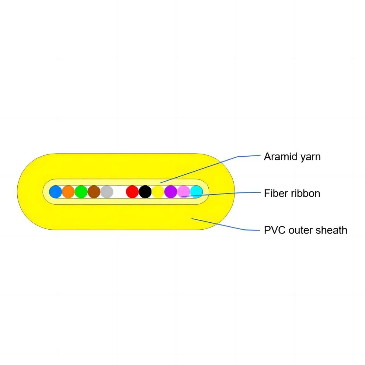
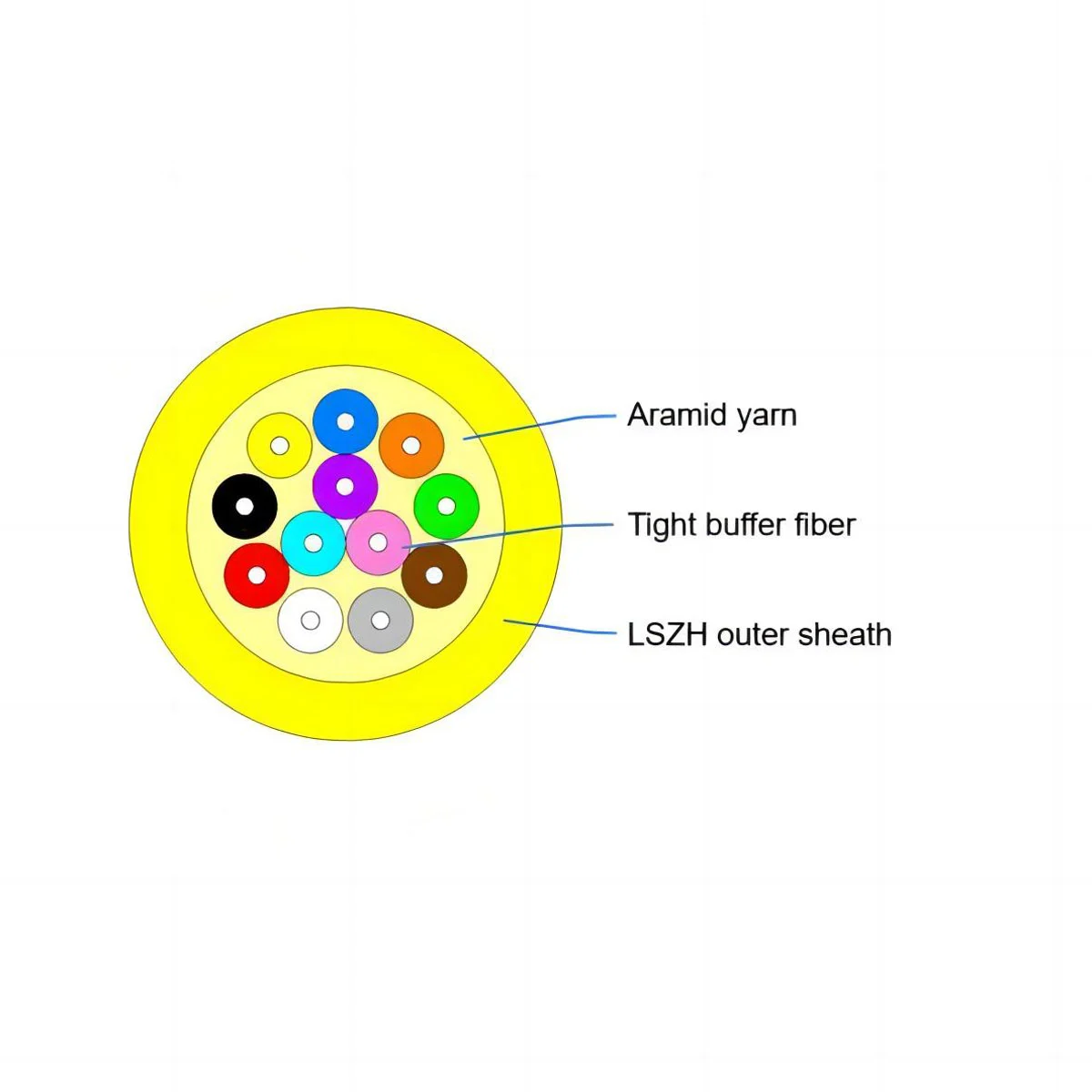
| Indoor fiber optic cables | Building wiring, telecom rooms and indoor routing | Provides the optical cable link inside premises and structured cabling systems. |
| Outdoor fiber optic cables | Outdoor backbone, campus networks and telecom routes | Connects outside plant routes with indoor termination and distribution systems. |
Need Help Selecting Fiber Patch Cords and Patch Panels?
If you are preparing a fiber optic cabling project, share your fiber type, connector type, port count, rack layout, patch cord length, polarity plan and testing requirements with HDC. This helps our team recommend suitable fiber patch panels, jumper couplers, patch cords and cable products for your project.
Whether your project is for a data center, telecom room, enterprise building, campus backbone or FTTH distribution network, HDC can help you build a more organized and reliable fiber cabling system.
Contact HDC for fiber cabling component selection support
FAQ About TIA-568.3, Fiber Patch Cords and Patch Panels
What is TIA-568.3 used for?
TIA-568.3 is used for optical fiber cabling and components in premises cabling systems. It covers optical fiber cables, connectors, connecting hardware, patch cords, performance, transmission, testing and polarity-related requirements.
Does TIA-568.3 apply to fiber patch cords?
Yes. TIA-568.3 includes patch cords within its scope. For buyers, this means fiber patch cords should be selected according to fiber type, connector type, performance requirements, polarity and cabling channel compatibility.
Does TIA-568.3 apply to fiber patch panels?
Yes. Fiber patch panels are part of connecting hardware in optical fiber cabling systems. They help terminate, organize and manage fiber links in racks, cabinets, telecom rooms and data centers.
Why is polarity important in fiber optic cabling?
Polarity ensures that the transmitter at one end connects to the receiver at the other end. If polarity is wrong, the optical link may fail even when the physical connectors are plugged in correctly.
How should buyers choose a fiber patch cord?
Buyers should confirm fiber type, connector type, polarity, insertion loss, jacket material, length, color coding and compatibility with patch panels, adapters and transceivers.
How should buyers choose a fiber patch panel?
Buyers should confirm port capacity, connector type, adapter type, rack compatibility, cable management design, labeling method, splice tray requirements and project environment.
Should patch cords and patch panels be purchased together?
For project reliability, patch cords and patch panels should be planned together. Matching connector type, fiber type, polarity and port layout helps reduce installation problems and improves long-term network maintenance.

 Call us on:
  Email Us:
  No.10 Xumutang Road, Lishui Economic Development Zone, Nanjing, China